- TOP
- Fundamentals of CAE
- Part 3: Introduction to CAE software
Series: Fundamentals of CAE Analysis for Plastic Product Design
Part 3 Introduction to CAE software
The purpose and application of each analysis field will be explained, and typical software and software used at Asahi Kasei will be introduced.
Contents
Introduction
Many software companies in Japan and overseas have released a wide variety of software for CAE analysis. There are differences depending on the software, such as what kind of analysis can be done, the field of expertise, and the support system, so it is important to choose the appropriate analysis software that matches the purpose and application.
This time, we will explain the software used for CAE analysis of plastics. We will introduce representative analysis software for each field of analysis, as well as the software used at Asahi Kasei.
Injection molding simulation (flow warp analysis)
This is a simulation to determine whether flow is possible, to study optimal gate position, to predict warpage, to predict molding cycles, to predict mold clamping force, and to design cooling pipes with good cooling efficiency.It is also called resin injection molding analysis, and is a common analysis for analyzing plastic products in product design and mold specification design.
Warpage deformation is one of the serious molding defects. Warpage is caused by uneven resin shrinkage within the cavity. In other words, the shape of the molded product and gate position must be designed so that the temperature and pressure are uniform within the cavity, and the mold cooling pipes must be arranged so that there are no temperature differences within the mold.
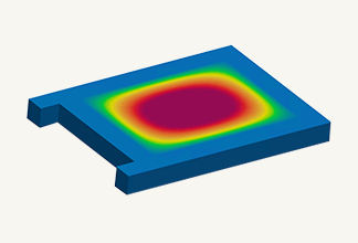
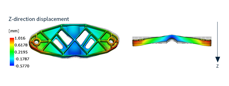 Fig. 1 warpage analysis example (warp prediction)
Representative software includes "Moldflow" from Autodesk, "Moldex3D" developed by CoreTech System, and "3D TIMON" developed by Toray.
Asahi Kasei uses the widely used "Moldflow".
Stress analysis
It is used to predict the amount of deformation, stress, strain, presence or absence of failure, and failure load when a load is applied. In mechanical design, it is necessary to know strength of the product, and it is a highly important analysis. Because it is possible to simulate before actually creating a sample and conducting a strength test, it leads to a reduction in the design development period.
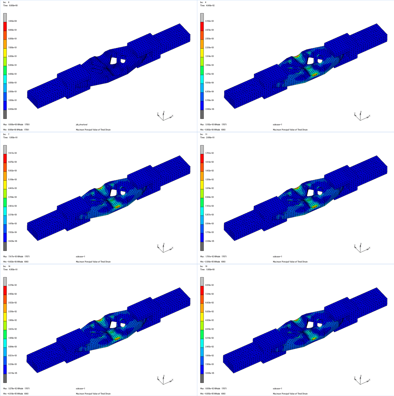 Fig. 2 Example of stress analysis
Stress analysis is explained in more detail in another chapter.
Representative software includes Dassault Systèmes' "Abaqus," Siemens Software's "NX Nastran," Ansys' "ANSYS," and Altair's "OptiStruct," but there is a wide variety of software available.
Asahi Kasei uses "Abaqus" and Hexagon's "Marc".
Experience Your First Structural (Stress) Analysis Simulation
Thermal transfer analysis
Analyze how heat is transferred inside the solid and simulate the temperature distribution. Analyze how heat is transmitted in parts where heat is applied and parts in contact with heat-generating parts. You can evaluate the heat insulation and heat retention of Materials.
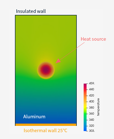 Fig. 3 Example of heat conduction analysis
Thermal stress analysis
Predict stresses caused by temperature changes.
As mentioned in "2.Differences between plastics and metals Temperature characteristics" in Part 2 Plastics CAE, plastics have a higher coefficient of linear expansion than metals, and are more affected by thermal stress. Special care must be taken when combining materials with different coefficients of linear expansion.
It is also possible to perform a coupled analysis in which the temperature distribution is obtained in a heat transfer analysis and used as a boundary condition in a stress analysis.
Thermal conduction analysis and thermal stress analysis can be calculated with most of the stress analysis software mentioned above.
Thermo-fluid analysis
Predict how fluids, such as liquids and gases, flow in and out of objects. In the case of products that actually generate heat, the heat is not only transferred inside the solid, but also occurs through heat-bearing fluids (air, oil, etc.) to other parts. Such phenomena cannot be analyzed by thermal conduction analysis, so thermal fluid analysis / Computational Fluid Dynamics(CFD) is used.
Also, even if the part has a complicated shape, thermal fluid analysis / Computational Fluid Dynamics(CFD) is effective because the heat conduction coefficient and temperature distribution change due to the convection of the surrounding air.
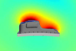
 Fig. 4 Thermo fluid analysis / Computational Fluid Dynamics(CFD) example
Representative software includes Altair's "AcuSolve," Ansys's "ANSYS Fluent," Siemens Software's "STAR-CCM+," and Convergent Science's "Converge."
Asahi Kasei uses "AcuSolve".
Eigenvalue analysis (Natural frequency analysis)
Calculate the eigenfrequency and eigenmode shape of the object.
The natural frequency is the number of vibrations per second when an object (vibrating system) vibrates freely. The eigenmode shape is the shape (deformation) of vibration when vibrating at the eigenfrequency.
If the object resonates, damage or noise may occur. Resonance is a phenomenon in which vibrations are greatly amplified by receiving external vibrations that are the same as the natural frequency of an object. It is possible to find the frequency at which resonance is likely to occur by natural frequency analysis, and it is used to design structures that do not cause resonance.
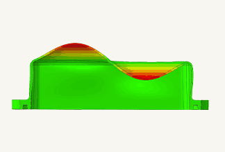
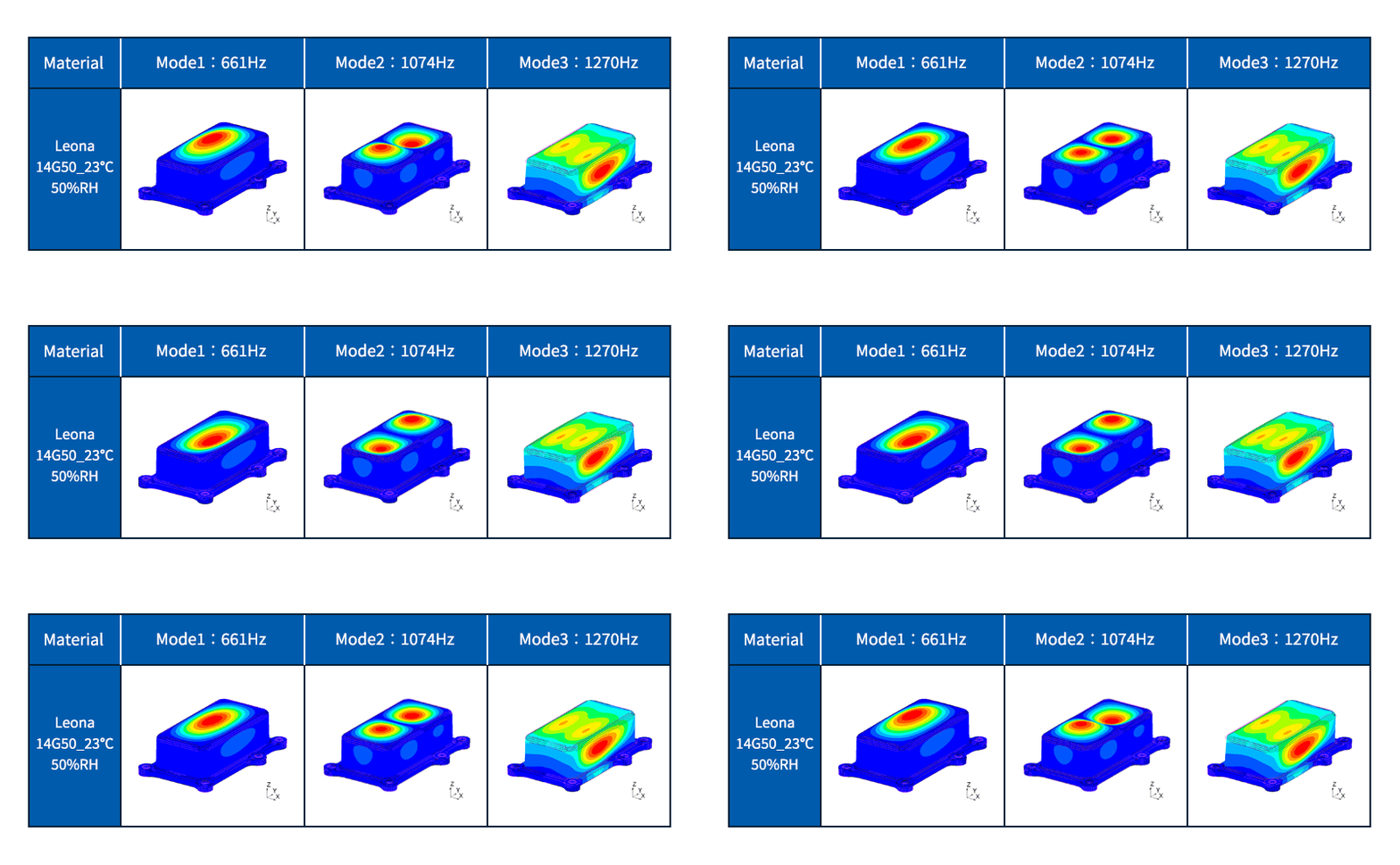 Fig. 5 Example of eigenvalue analysis (natural frequency analysis)
(Frequency) Response analysis
Simulate the displacement and stress generated when an object is excited.
When resonance occurs, it is possible to obtain the amount of amplitude and stress generated, and to check the effect of taking measures against resonance.
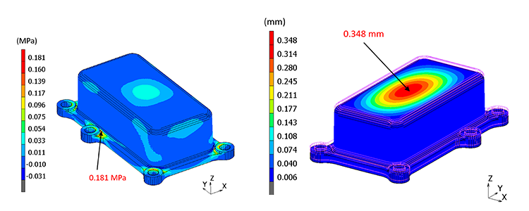 Fig. 6 (Frequency) response analysis example
Representative software for eigenvalue analysis (natural frequency analysis) and (frequency) response analysis include "Abaqus" from Dassault Systèmes, "NX Nastran" from Siemens Software, and "LS-DYNA" from Ansys.
Asahi Kasei uses "Abaqus" and Hexagon uses "Marc".
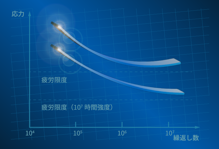
Cyclic fatigue analysis
Predict the number of times until failure occurs when a repeated load is applied.
When a load is repeatedly applied to an object, even a stress smaller than its static strength may cause it to fail. This is called fatigue failure, and can be evaluated using an SN curve.
Simulations can be performed before actual samples are created and durability tests are performed, leading to a reduction in development time.
Creep analysis
Predict the amount of creep deformation after a certain period of time.
As mentioned in the 2nd plastic CAE point "2. Differences between plastics and metals Viscoelastic properties <creep>", plastics are strongly affected by creep loads due to their viscous properties, so countermeasures are taken by performing simulations in advance. can do. It is also used for life prediction of solder joints.
Stress relaxation analysis
Predict the stress value after a certain time. As explained in "2.Differences between plastics and metals -Viscoelastic properties <stress relaxation>" in the 2nd plastic CAE, stress relaxation is a phenomenon that occurs due to the viscoelastic properties of plastics.
Care must be taken when designing parts that are fixed with screws or bolts, or products that use reaction force generated by intentionally deforming, such as springs. Unlike creep, changes cannot be seen from the outside, so pre-analysis can prevent quality problems.
Representative software for cyclic fatigue analysis, creep analysis, and stress relaxation analysis include "Abaqus" from Dassault Systèmes, "NX Nastran" from Siemens Software, and "LS-DYNA" from Ansys.
Asahi Kasei uses "Abaqus" and Hexagon uses "Marc".
Impact analysis
It simulates time-history stress, strain, displacement, acceleration, etc. when an object collides or falls. When an object receives an impact, stress many times greater than the static stress value is generated, causing damage and other problems.
In addition, it is possible to perform an evaluation that considers the dynamic properties (strain rate dependence, viscoelastic effect) unique to the material. Strain rate dependence is a property of resin that material properties vary greatly depending on the deformation rate.
It is used for tests assuming the collision speed of automobiles, etc.
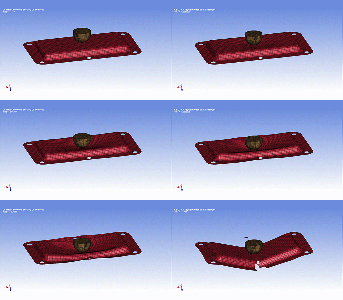 Fig. 7 Example of impact analysis
Representative software includes Ansys's "LS-DYNA," ESI's "PAM-CRASH," and Altair's "Radioss."
Asahi Kasei uses "LS-DYNA."
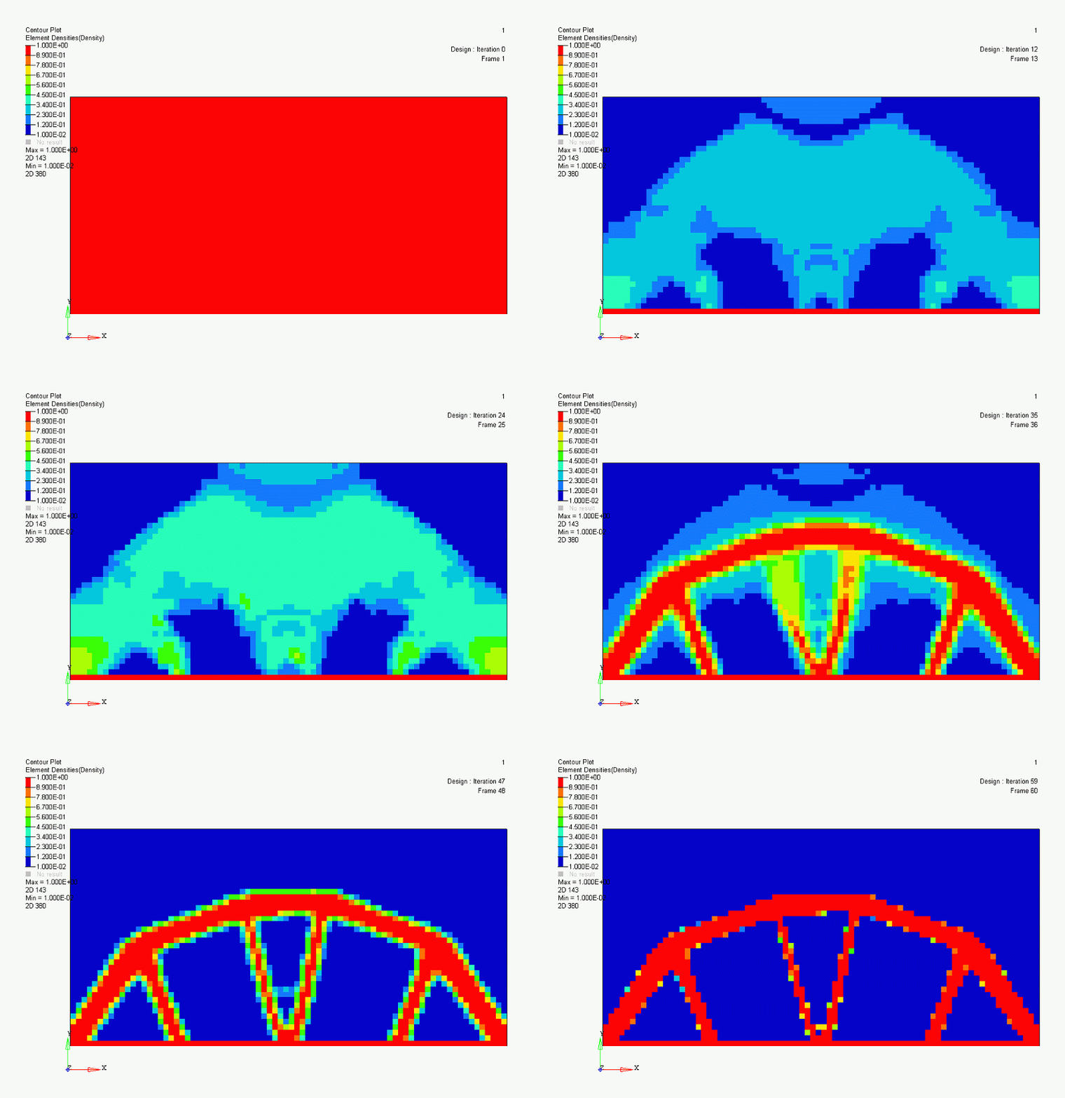
Topology Optimization
Topology optimization is a system that calculates optimal shape by giving the structural constraints, loads, and constraint conditions expected in the product's usage scenario.
Highly novel shapes that cannot be conceived by humans are generated, leading to product designs that are not bound by existing shapes.
It can be said that it is a technology that will attract more and more attention in the future due to the progress in production and processing technology such as 3D printers.
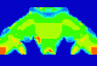
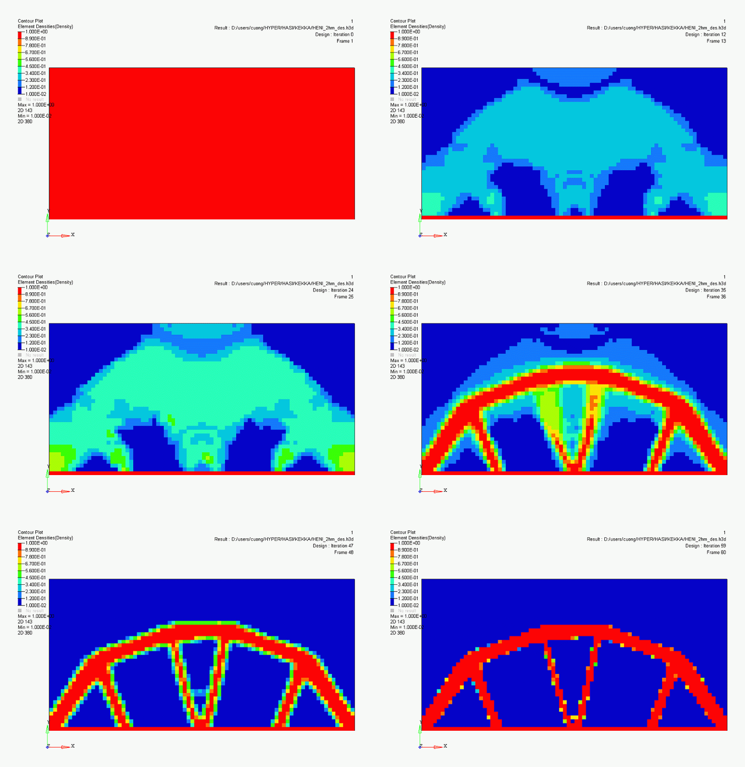 Fig. 8 Example of shape design using Topology optimization
Representative software includes Altair's "OptiStruct" and Dassault Systèmes' "TOSCA."
Asahi Asahi Kasei uses "OptiStruct".
Acoustic analysis
We analyze and visualize various acoustic phenomena related to sound generation and propagation.
In addition to improving the sound quality of audio equipment such as speakers, it is possible to reflect measures against unpleasant sounds such as noise from industrial products such as engines and fans in the design. This analysis is indispensable for the development of products with excellent acoustic characteristics and products that require quietness.
Fig. 9 Acoustic analysis example
Representative software includes Hexagon's "Actran" and Dassault Systèmes' "Abaqus."
Asahi Kasei uses "Actran."
Mechanistic analysis
In normal analysis using the finite-element method, evaluation is performed for individual parts. However, for products that combine multiple parts, it is necessary to analyze the parts as a set.
In Multibody dynamic analysis, it is possible to predict the influence of joint force with other parts and the acting force, and simulate what kind of force is acting by further movement.
It is used to evaluate mechanical systems in which multiple parts are intricately connected, such as automobiles and industrial equipment.
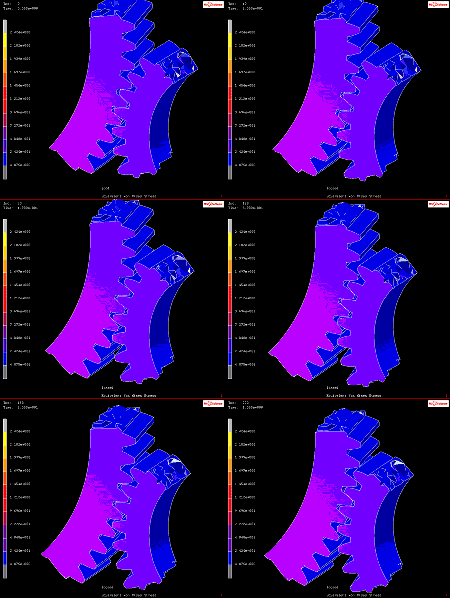 Fig. 10 Multibody dynamic analysis example
Source: Model in the video of “Contact Analysis”, “Disruption and Damage Analysis”(Viewed February 26, 2021).https://www.mscsoftware.com/product/marc
Representative software includes "Simpack" from Dassault Systèmes and "Adams" from Hexagon.
Asahi Asahi Kasei uses "Adams".
Fiber orientation mapping
Fiber orientation must be taken into consideration when designing reinforced grades in which glass-fiber are mixed with resin. This is because the orientation of the fibers is determined along the flow of the resin, resulting in uneven shrinkage and warping, as well as areas with weak strength and directions. The accuracy of stress analysis can be improved by mapping fiber direction and orientation information from injection molding analysis results and transferring it to another analysis software.
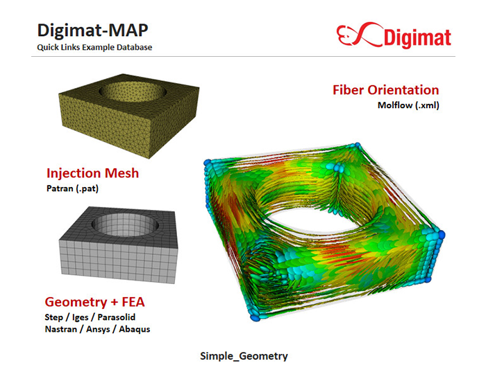 Fig. 11 Example of Fiber orientation mapping
Source: Fiber orientation mapping model on Hexagon website (January 16, 2023)
A typical software is Hexagon's "Digimat."
Asahi Kasei uses "Digimat."
Next Part: "Injection molding simulation - What is injection molding?"
For more information about CAE, please contact us.
CAE Download Slides
