Solutions
Engineering-plastic foams for improved thermal management in electronic devices:

What is SunForce™?
SunForce™ products are foam beads made from XYRON™ modified PPE resins that combine the excellent physical properties of modified PPE resins—including heat resistance, dimensional stability, and low water absorption—with the light weight and good excipient properties (shape flexibility) of beaded foams.
Because SunForce™ products are produced by in-mold foaming, they are also ideally suited for mass production.
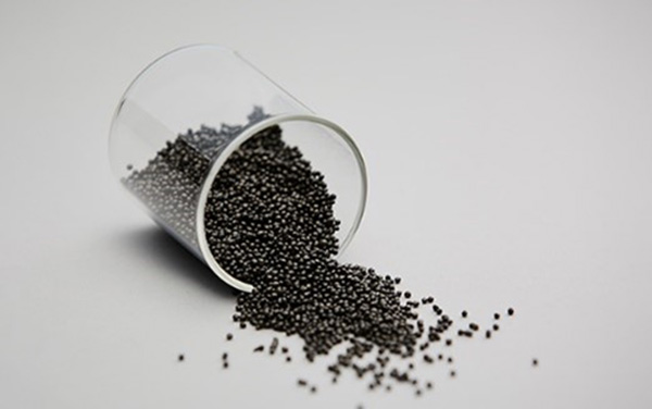
In addition, the independent-bubble structure of SunForce™ foams makes these materials excellent thermal insulators.
| Material | Thermal conductivity (W/m・K) | Material | Thermal conductivity (W/m・K) | Material | Thermal conductivity (W/m・K) |
|---|---|---|---|---|---|
| Carbon nanotubes | 5500 | LCP (Liquid Crystal Polymer) | 0.56 | SunForce™ (x5) | 0.041 |
| Diamond | 2000 | FRP (Fiber Reinforced Plastic) | 0.26 | Cellulose fiber | 0.040 |
| Copper | 370 | PPS (Polyphenylene Sulfide) | 0.26 | Rockwool | 0.038 |
| Aluminum | 200 | Polycarbonate | 0.19 | SunForce™ (x7) | 0.038 |
| Graphite | 120 | ABS | 0.19 | Glass wool 32K | 0.036 |
| Iron | 80 | Polyvinylchloride (PVC) | 0.17 | Melamine foam | 0.035 |
| Carbon-copper | 41 | Plywood | 0.16 | SunForce™ (x10) | 0.034 |
| Alumina | 32 | Particle board | 0.15 | Extruded polystyrene foam (Type 3) | 0.028 |
| Stainless steel | 16 | Modified PPE | 0.15 | Hard urethane foam (Type 1 #1) | 0.024 |
| Carbon fiber-reinforced plastic | 4.7 | Polystyrene | 0.15 | Air | 0.022 |
| Zirconia | 3.0 | Cypress wood | 0.095 | Silica aerogel | 0.017 |
| Concrete | 1.6 | Cedar wood | 0.087 | Carbon dioxide | 0.015 |
| Glass | 1.0 | Cork | 0.043 | Vacuum insulation material | 0.002 |
| Water | 0.58 | – | – | – | – |
In what follows we present two illustrative applications exploiting the unique properties of SunForce™ foams to improve thermal management in electronic devices.
Sample application 1:
Thin-walled, complex-shaped insulation materials
SunForce™ is well-suited for mass production of thin-walled, complex-shaped insulation materials due to its high heat resistance and flame retardancy (certified to UL94 V-0 standards) derived from the material. It is formed by in-mold foaming using small-diameter beads as raw material. This allows for the mass production of insulation materials that fit the complex shapes of components.
| Foam Type | SunForce™ | EPS (Expanded Polystyrene) |
EPP (Expanded Polypropylene) |
Urethane Foam Sheet |
|---|---|---|---|---|
| Forming Method | In-mold foaming | In-mold foaming | In-mold foaming | Extrusion foaming |
| Formability | ◎ | ○ | ○ | × |
| Thin-wall Forming | ○ | × | × | × |
|
Heat Resistance |
○ | △ | × | △ |
| Flame Retardancy | UL94 V-0 | Flammable | Flammable | Flammable |
For applying insulation to complex components, glass wool or urethane foam is commonly hand-applied by workers. However, using SunForce™, not only enhances heat management efficiency through high thermal insulation but also contributes to condensation prevention, reduction of the number of parts (saving labor and costs), and improved productivity and assembly precision (ensuring stable product quality) during assembly.
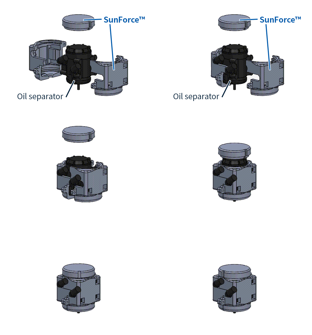
These characteristics allow SunForce™ to be applied across a wide range of fields that require high performance and high safety, such as cooling components for automobiles, cooling parts for 5G/6G communication devices and solar power conditioners, water cooling components for data centers and AI servers, engine oil separators, and air conditioning ducts.
Sample application 2:
Heat shielding material using SunForce™
Our first example uses SunForce™ heat shields to achieve thermal insulation in an electronic circuit board with highly heat-emitting components (such as might be found in a PCS unit in a solar-power generator).
SunForce™ foams make them ideal materials for heat shields to isolate heat-emitting regions from non-heat-emitting regions of electronic circuit boards.The excellent thermal insulation, extensive shape flexibility, flame retardance, and heat resistance of
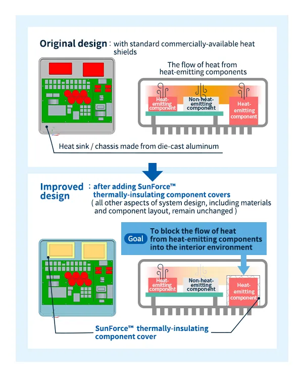
The figures below show the temperature distribution inside an electronic device, computed using a thermal-analysis simulation model, before and after the addition of thermally-isolating SunForce™ heat shields to isolate highly heat-emitting components from non-heat-emitting components. These results demonstrate how SunForce™ thermal-management solutions can achieve significant reductions in internal device temperatures.
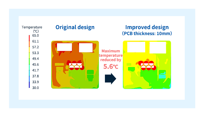
This example demonstrates how heat shields made from SunForce™ foams can simplify the miniaturization of electronic devices by reducing operating temperature, preventing component degradation, and allowing greater flexibility in component layout.
Sample application 3:
SunForce™ thermally-isolating ducts
Our second example involves the installation of thermally-isolating SunForce™ ducts on an electronic circuit board equipped with highly heat-emitting components. This complements the heat-shield example discussed above by presenting an alternative way in which the unique properties of SunForce™ foams can be exploited to improve thermal-management performance in electronic devices.
Differences in the operating temperatures of electronic components give rise to convection airflows inside electronic devices. In some cases, various factors—such as the layout of components or the temperature distribution within the device—may conspire to obstruct the flow of air through particular device regions, degrading the performance of cooling mechanisms and causing component temperatures to rise.
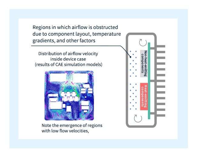
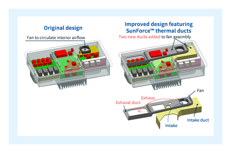
The problem of obstructed airflow arises in the specific system considered in this example: a solar-cell PCS unit equipped with an internal cooling fan, depicted schematically at the left in the figure below. To alleviate this problem, we improved the design by installing thermally-isolating SunForce™ ducts around the fan unit, as shown at the right below.
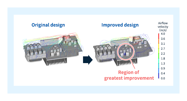
The streamline diagrams below show simulated airflows through the electronic device before and after the addition of SunForce™ ducts. Comparing these plots, we see that the ducts create new pathways for air to flow through the device, ensuring smoothly-controlled airflows at all stages from intake to exhaust. The improvement in airflow quality is particularly significant in the vicinity of heat-emitting components.
The simulated temperature distributions are plotted below: The controlled airflow enabled by the presence of the ducts yields significant reductions in component temperatures.
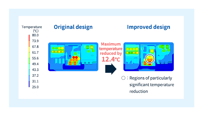
This example demonstrates how thermally-isolating ducts made from SunForce™ foams can improve airflow control in electronic devices, thereby reducing component temperatures, preventing component degradation, and allowing greater flexibility in component layout.

