- TOP
- 技術サポート
- Examples of CAE results
- Pursuing strength and precision: Designing gears with fiber-reinforced resins

Injection molding analysis
Pursuing strength and precision: Designing gears with fiber-reinforced resins
Contents
Summary
- We present a real-world case study in which resin CAE analysis was used to design a worm wheel made from glass-fiber-reinforced polyacetal.
- Flow-based warp analysis was used to characterize the design’s roundness—one key measure of dimensional precision—and confirm that the design achieved the requisite specifications.
- By changing to the optimal shape, we were able to reduce the weight by 23% while maintaining the strength.
Introduction
In comparison to conventional non-reinforced plastics, glass-fiber-reinforced materials offer the advantage of superior strength, but with the drawback of higher specific gravity due to the presence of the glass fibers. An additional complication of working with glass-fiber-reinforced materials is the need to account for the orientation of the glass fibers during the design process.
Here we present a real-world case study in which we applied resin CAE techniques to the redesign of a worm wheel using glass-fiber-reinforced polyacetal. Our redesign process successfully identified a modified component shape that reduced overall weight while retaining performance equivalent to that of the original component. Moreover, because dimensional precision is particularly important for worm wheels, we used flow-based warp analysis to characterize the roundness—one key measure of dimensional precision—of the redesigned component, thus confirming that the revised design satisfied all product specifications.
Purpose
Modify component shape to reduce overall weight
Confirm the roundness of the revised component shape
Redesign proposal
As shown in Figure 1, the original component design relied on ribs to achieve sufficient strength. Our revised design was able to eliminate these ribs thanks to the use of glass-fiber-reinforced polyacetal, which has an elastic modulus 2.8 times greater than that of the original component material. This demonstrates how the use of high-rigidity materials can simplify component shapes.
Although the density of the component material increased by 9%, the elimination of ribs reduced the overall component weight by 23%.
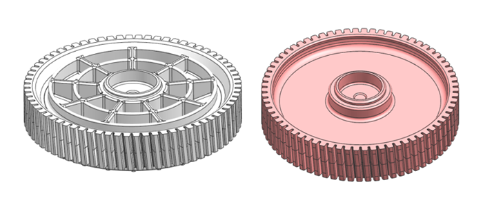
Figure 1: Original component (left) and redesigned component (right).
Analysis
We characterized roundness using the fluid-flow analysis conditions listed in Figure 2.
The original component was made from a material provided by an outside firm. The redesigned component was made from a glass-fiber reinforced grade of Asahi Kasei’s TENAC™-C.
The roundness of a nearly-circular component measures the deviation of the component from a geometrically perfect circle (JIS B 0621-1984). Because gears rely on an extremely delicate mechanism of torque transfer—involving careful meshing between the three-dimensional shapes of multiple gear teeth—discrepancies in tooth shape can degrade torque-transfer performance. Thus the tip diameter for each gear tooth must be carefully measured to ensure that gears resemble perfect circles as closely as possible.
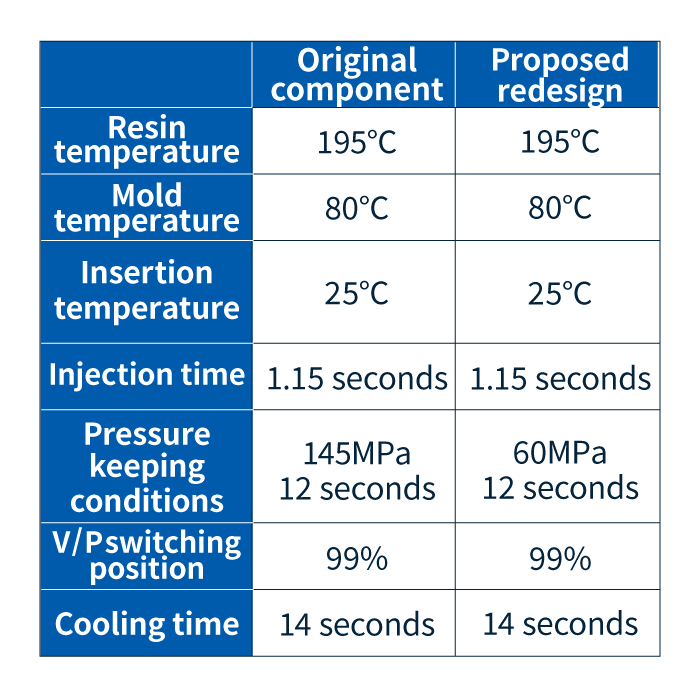
Figure 2: Analysis conditions
Results
As shown in Figure 3, we characterized the roundness of our redesigned component at three positions—top, middle, and bottom—and determined that the mean deviation was just 0.03 mm, well within the specified tolerance for this component. Thus our proposed redesign satisfied all product specifications (Figure 4).
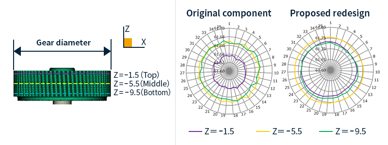
Figure 3: Positions (left) and results (right) of roundness assessments.
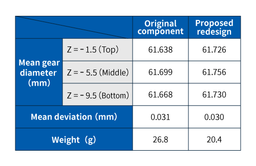
Figure 4: Results of roundness assessments.
What are worm wheels?
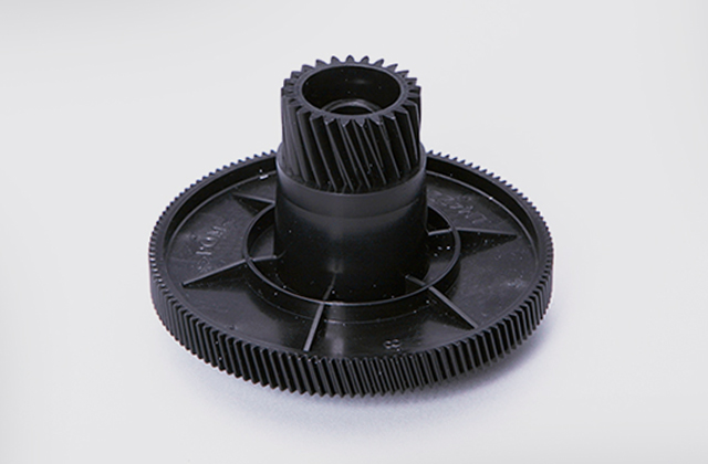
Gears with slanted teeth used in worm gears(worm drives) are known as worm wheels. A worm gear is an assembly in which a worm—a cylindrical bar imprinted with slanted teeth resembling screw threads—meshes at a 90-degree angle with a worm wheel. The characteristic features of worm wheels are that their teeth have unusual cross sections—designed as if intended to slowly devour worms—and are slanted to mesh with the slanted threads of the worm. The advantages of worm gears include their large speed reduction ratios and their high output torque; their drawbacks include susceptibility to abrasion and friction-induced heat generation.
The glass-fiber-reinforced resin grade used in this design revision exhibits reduced abrasion compared to conventional reinforced materials—a key property that motivated the direction we took in arriving at our proposed redesign.
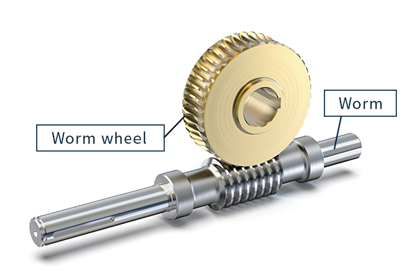
Figure 5: Worm gears
For further questions regarding CAE analysis—or to discuss the details of your design revision—please do not hesitate to contact us.


